Punch! SharkCAD Pro v14 Upgrade from SharkCAD Pro version 12
Dive into the exciting possibilities of CAD design with SharkCAD® Pro. Built with engineering and design professionals in mind, SharkCAD Pro gives you maximum power and flexibility with 2D drafting tools, 3D solid and mesh modeling, photorealistic rendering, and everything you need to create precision designs. Take a bite out of your competition with SharkCAD Pro.
Whether you are building model airplanes or real ones, SharkCAD Pro gives you a full stack of CAD design tools to go from concept to completion. Draft, diagram, and document your ideas in 2D view. Model, render, and print in 3D. SharkCAD Pro revolutionizes CAD design for printing, rendering, animation, and precision design. From small scale prototyping to large scale manufacturing, SharkCAD Pro can get it done.

As low as
$399.99
Availability:
In stock
SKU
4525-3
SharkCAD: Bigger, better, faster 2D/3D CAD software
Don’t waste another minute on entry-level software you’ve outgrown. SharkCAD can give you professional quality CAD design tools that won’t cost you an arm and a leg. Enjoy the flexibility of mesh-based modeling coupled with subdivision technology that will make creating conceptual drawings a breeze. SharkCAD also has 2D switching, so you can swim back and forth between 2D and 3D views as needed.
SharkCAD can help you design projects such as:
|
 |
Compatibility and file sharing
SharkCAD software plays nice with others. SharkCAD is compatible with AutoCAD® and over a dozen popular CAD and Graphics formats, so you will be able to easily collaborate with other professionals.
- SharkCAD provides compatibility with AutoCAD® DWG files
- DXF/DWG versions from R12 to 2019
- STL Import/Export for 3D printing
- SVG Import and Export
- 3MF Import & Export
- VMRL 2.0 Texture Support
- OBJ Texture Support
- Adobe Illustrator® Import
- PDF Import
- SketchUp 2019 Import/Export
- Collada™ (DAE) Import/Export
We will help you learn
While SharkCAD is feature rich, we work hard at making it easy by including intuitive tools like our LogiCursor™ that makes CAD a snap by suggesting your next move as you draw.
Your purchase also includes access to our training tutorials, so you will not have to learn through trial and error. We are experts at creating CAD software and our tutorials will help you to become an expert user quickly.
Simple and flexible pricing
We offer SharkCAD in two different pricing models to best suit your needs.
Permanent License - Download once and own it forever. Ideally suited for users who need a single license or users who feel they may not need to upgrade each year.
Annual Subscriptions - This is ideal for multiple user seats. With an active subscription, you will always be receiving the latest enhancements and new functionality.
Write Your Own Review
Sink your teeth into some of SharkCAD’s key features
Jump into the exciting world of 3D mesh modeling, coupled with 2D drafting tools, and you’ll be hooked. Some of the features that make SharkCAD the best choice for professional CAD design:
- Design complex organic shapes with extensive NURB surface modeling tools
- 2D Geometric and Dimensional Constraints to manage geometrical relationships between 2D shapes

- Push/Pull Modeling allows 3D surfaces to be edited with your mouse and cursor
- Powerful 3D editing tools such as blending, chamfering, and shelling

- Architectural and woodworking tools such as rabbet, miter and dovetail joints
- Extensive 2D drafting tools such as text, dimensions, 3D to 2D drawing, bill of materials
- Multiple Viewports provide 2, 3 even 4 views of your design and drawing between them
- Integrated Photo Realistic Rendering and support for Keyshot LiveLinking™
- And much more!

Intuitive Design and Editing Utilities
Drawing precisely is easy with SharkCAD! We have designed it to be user friendly and intuitive to work with.
The LogiCursor™ anticipates your next action and guides your cursor to potential point selections in the drawing.
The Gripper adds drag and drop capabilities to make editing designs easy breezy.
Customizable Grids add another level of ease by providing precision drag and drop in rectangular, polar (circular), and isometric layouts.
Precision Drafting and Annotations
SharkCAD is also a robust design documentation tool with over 20 customizable dimension styles, including industry dimension formats.
Other great features to help you document and annotate your projects include:
- 26-dimension styles
- Import bitmaps for logos and reference images
- Spell check is provided for another level of accuracy
- Single click Fills and Hatch
Architectural Planning Tools
SharkCAD includes all the professional level architectural tools you and your team need to draft, print, and collaborate on projects together.
- Architectural wall tools
- Composite walls to show materials
- Parametric doors and windows
- Instant 3D walls, roofs, and floor slabs
- Compatibility with AutoCAD® DWG files
- ACIS®-based geometry means you are creating with the same technology as software that costs thousands of dollars
Woodworking Tools
SharkCAD includes tools to speed up your woodworking projects. You can quickly create otherwise tedious joints such as Dado joints and miter joints.
- Joints including rabbet, miter, and dovetails
- Dado joints including options for through, stopped or blind
- Edge treatments including cove, round, bullnose, Dupont, waterfall, Ogee, and custom
- Tongue & Groove
3D Modeling Tools
SharkCAD provides powerful solid modeling technology found in many higher-end products. Additionally, SharkCAD delivers surface modeling tools to expand design capabilities.
- Feature-based History Tree for editing
- A complete design tool with extrusions, Booleans, surface modeling for more complex smooth surfaces
- Precise geometry suitable for 'concept to manufacturing'
- Associative surface modeling
3D Printing Tools
SharkCAD includes 3D printing tools to prepare and validate your designs to make them 3D printer ready.
3D Print Check
Checks for print viability, displaying warnings or errors to the user.
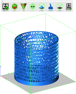
Surface Normals Check
Facet normals define the inside and outside areas of a part. If facet normals are pointing the wrong way, the 3D printer may have problems creating the part. This will check for problems and we have several commands that can help you fix it.
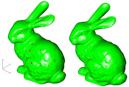
Overhang Analysis
This will help you visually inspect modeling areas that may require structural support for 3D printing. Meshes, surfaces, and solids facets normals are compared to the work plane direction. Angles that are less or equal to 45 degrees are highlighted as red.
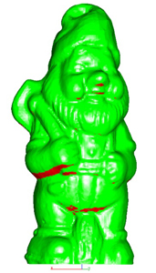
Wall Thickness Analysis
This tool provides a means to visually inspect modeling areas that may be too thin for 3D printing. Meshes, surfaces, and solids facets are examined using ray intersections.
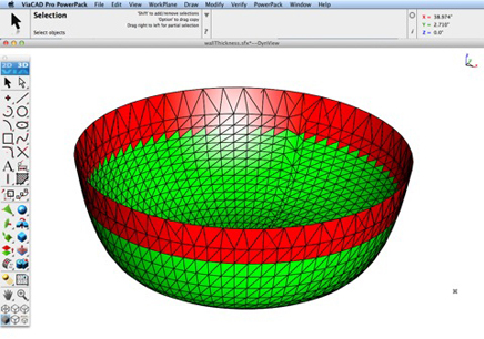
Preview Slices
This interface will help you to slice models given a direction and thickness. The dialog box allows for animation through the slices and single-stepping. Use to verify that a part has closed, non-overlapping sections, a requirement for 3D printing.

Auto Position
The Auto Position tool translates the model to the positive x, y coordinate system at z=0.
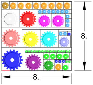
Support Structure
Manually adds geometry to support material as it is created by the 3D printer. Support structures controls, include Attach Radius, Midpoint Radius, Base Radius, Base Thickness, and Drag base and midpoints to modify structure location.
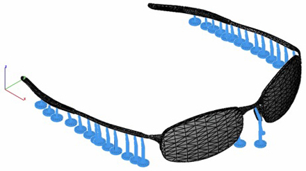
Show Printer Volume
Toggles the boundary of the default 3D Printer. The volume is defined within the Printer Definitions dialog box.
Printer Definitions
Sets key parameters of the 3D printer, including length, width, and height of the volume accessible by the printer. The parameters in the Printer Definitions dialog box are used for commands such as 3D Print Check and Auto Position.
SharkCAD Pro version 14 is here!
You are going to love the new features we have included in our latest release.
PowerPack Now Included!
SharkCAD v14 is packed to the gills with new features. We took our popular PowerPack add-on and baked it into our version 14 release at no additional cost to you. That adds a collection of over 70 new tools including 3D printing repair tools, new modeling tools and general utilities that will increase productivity and make your existing and future designs 3D Printer ready.
Read about some of our most exciting new features below.
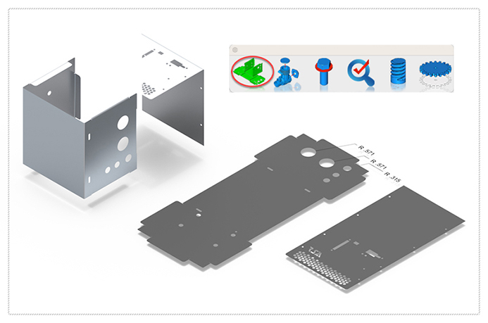
Unfold Sheet Tool
The Unfold sheet tool is used to flatten analytical or NURB surfaces into the xy plane. The unfold operation works on a sheet body that is flattened by mapping it onto a plane. The output body is a B-rep body consisting of planar faces and edges.
If the input sheet body is stretched and/or compressed during the unfolding, the shapes of features on the input body will be transferred faithfully to the output body, at the cost of some area distortion. The amount of distortion depends on the curvature of the input sheet body, as well as the constraints imposed by how faces are connected. Developable Surfaces (with zero Gaussian curvature), such as cylinders and cones can be unfolded without any area distortion. Other curved surfaces (with non-zero Gaussian curvature) may have some distortion during unfolding.
The unfold tool is in the mechanical tool palette located under Tools in the menu bar. Selecting the tool icon prompts the user for the surface or body to unfold. The surface to unfold fold must have zero thickness such as with a surface or mesh object. For example, it does not accept a solid. Select any surface in the body and the results are displayed in the XY plane at z = 0.
BOM Fraction Measurements
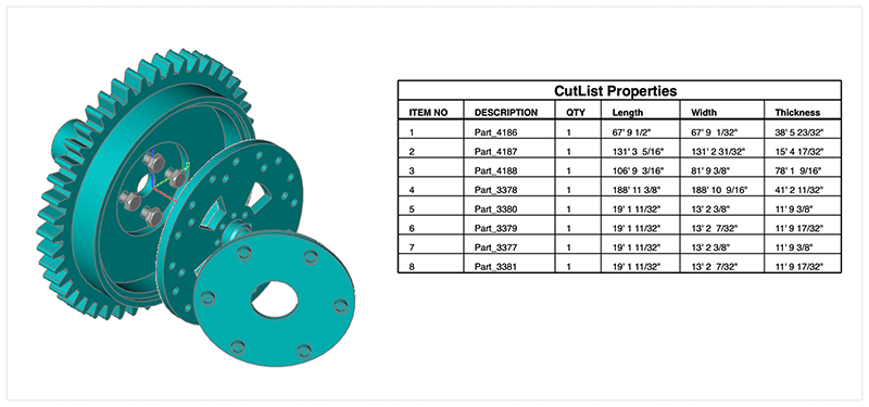
The Bill of Material Create BOM feature has a new option to support fraction measurements. To use this feature, select the Attributes and BOM dialog box from the Tools menu. Select your objects and associated a data set such as CutList properties. Apply to selected. Now select the Create BOM option to create a table. In the BOM Settings dialog box, select the Decimals pull down option. And then Select Fractions to display measurements as factions of feet and inches.
Clash Detection
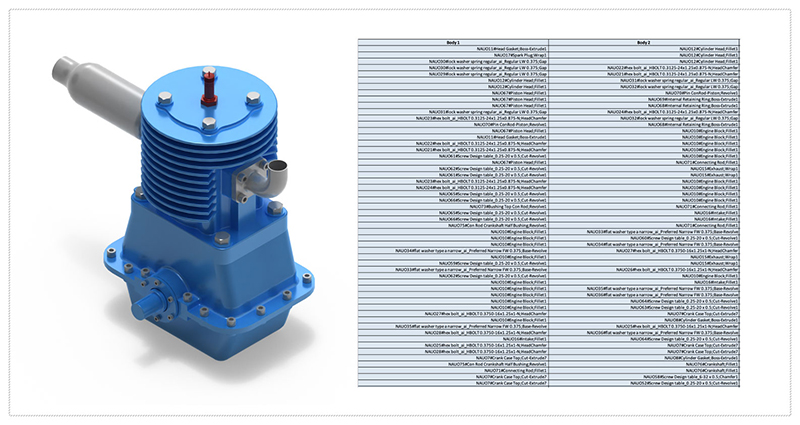
A ‘clash’ is the result of two objects in your design taking up the same space. A clash detection is the technique of identifying if, where, or how two or more parts of a grouping interfere with one another. Clash Analysis is suitable for checking mate, align, and interference checks for parts and assemblies. Example types of interference may be:
- volume sharing
- face sharing
- edge sharing
- vertex sharing
The Clash Detection tool will report up twenty different types of clashes.
Compare Parts
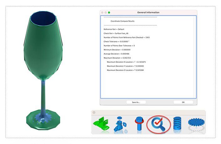
The Compare Parts tool examines two parts for deviations in geometry. Deviations are shown as minimum distance vectors between the two parts.
The first part selected must be a surface or solid. The second part must be a mesh which can be an imported object such as a STL, OBJ, or point cloud via the PLY file format. The result of the tool is provided as a report plus distant deviations represented by line entities between the two parts.
Gear
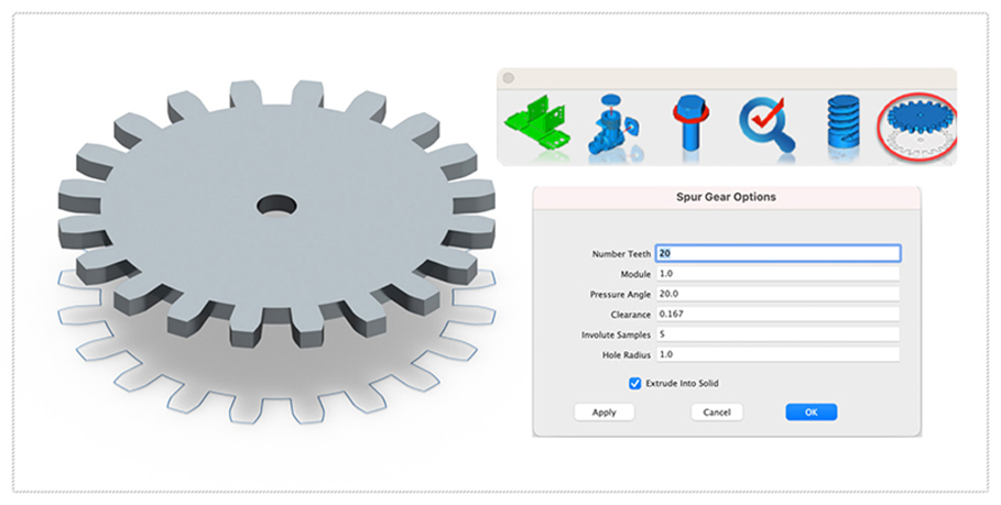
A spur gear is a type of mechanical gear with straight teeth that are parallel to the axis of rotation. Spur gears are used to transmit power and motion between parallel shafts. They are simple and inexpensive to manufacture, and they are widely used in many different types of mechanical systems.
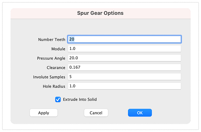
The Gear tool is in the Mechanical tool palette. A gear is created by specifying a variety of parameters displayed in the creation dialog box. .
Example
1. Select the gear tool from Mechanical tool palette
2. Specify a location for the gear center
3. The gear parameters dialog is displayed
4. Specify the parameters below:
- Number of Teeth
- Module
- Pressure Angle
- Clearance
- Involute Samples
- Hole Radius
5. Specify whether to create a 3D solid along with the 2D gear profile.
Enable the check box to create an associate 3D extrude solid with the 2D gear profile
PBR Photo Rendering
PBR, or physically based rendering, is a method of rendering computer graphics that aims to accurately represent the way that light interacts with different materials in the real world. In PBR rendering, the appearance of a material is defined by a set of parameters that describe its physical properties, such as its roughness, reflectivity, and transparency. These parameters are used to calculate the way that light reflects off the surface of the material, taking into account the angle of the light source and the surface normal, as well as the surface's roughness and other properties.
One of the key benefits of PBR rendering is that it allows for more realistic and consistent results, as it is based on the physical properties of real-world materials rather than arbitrary artistic choices. This makes it particularly well-suited for applications where photorealism is important, such as architectural visualization, product design, and film and game development.
Key user interface components to PBR rendering include:
• Photo Render Tool Palette
• Rendering Cameras
• Render To File
• Render Window
• Render Settings
For a quick introduction to Photo Rendering with V14 see the video below:
Photo Render Tool Palette
The Photo Render tool palette provides access to many of the tools used to create photo rendered images. The tool palette is access from the Tools menu bar “Photo Render” option.

| • Create Camera | Creates a camera from eye point, reference point, and field of view. Cameras are saved with file and used with the Render Camera tool. |
| • Render Camera | Renders a selected camera to the window. |
| • Render Window | Renders the current window and view orientation. |
| • Render To File | Renders current view orientation to a file with new width/height. |
| • Display Last Render | Displays the last rendered window to drawing window. |
| • Render Settings | Dialog box with settings for HDRI, background, materials, and other settings. |
Create Camera
The Create Camera tool creates a camera object from eye point, reference point, and field of view. Cameras are useful for saving view orientations that can be recalled or used with the Render Camera tool. To create a camera:
1.Select the Create Camera tool from the photo render tool palette
2.Specify the eye point, defined as the camera location
3.Specify the reference point, which specifies where the camera is looking
4.The camera is created
Camera objects have two parameters that can be modified from the data entry window.
1. Field of View (size of viewing area)
2.Focal length (length of camera and controls perspective distance)
Render Camera
The Render Camera tool creates a photo rendered image from a selected camera.
Camera properties supported when using this command include:
Start Point representing the camera eye point
End point representing the camera reference point
Field of View defines the scope of the view
Cameras are always rendered with perspective enabled. The rendered image is drawn into the drawing window.
Render Window
The Render Window tool renders using the current view orientation. The results are displayed into the drawing window.
Render To File
The Render Window tool renders using the current view orientation. The results are displayed into the drawing window.
Display Last Image
The Display Last Image redraws to the window the last photo rendered image.
Photo Realistic Render Settings
The Render Settings dialog provides access to the following photo render settings and parameters.
• General Settings
• HDRI
• Backgrounds
• Sun & Sky
• Textures
• Post Effects
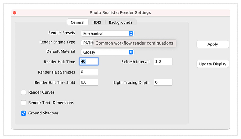
General Settings
The General Settings tab provides access to the following photo render settings and parameters:
| Render Presets | Presets parameters for mechanical, architectural, and jewelry scenes |
| Render Engine Type | Method of light tracing |
| Default Material | Glossy or Matte for parts with no materials assigned |
| Render Halt Time | Stop rendering after so many seconds |
| Render Halt Samples | Stop render after so many render passes |
| Render Halt Threshold | Render until pixels stop changing by this percent |
| Render Curves | Render curves as pipes |
| Render Text & Dimensions | Render Text and Dimensions as polygons |
| Ground Shadows | Create a transparent ground to catch shadows |
| Refresh Interval | Refresh the drawing screen only after so many seconds |
| Light Tracing Depth | The maximum number of light bounces |
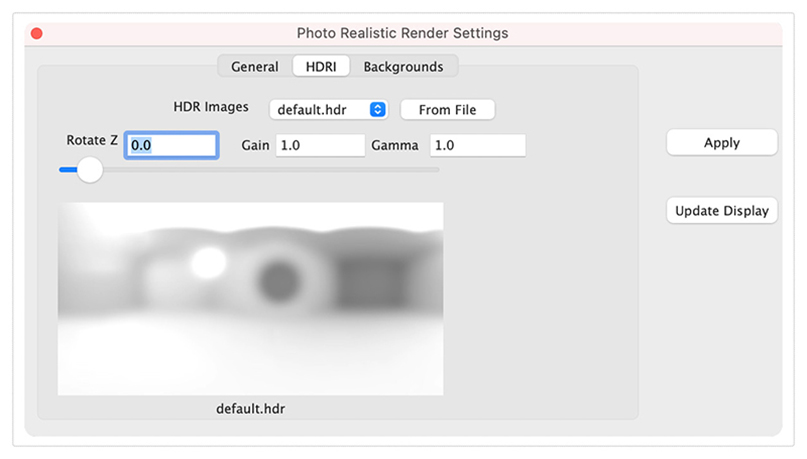
HDRI
The High-Definition Range Image (HDRI) tab provides access to the following settings and parameters:
| HDR Images | Drop drown containing example HDRI images |
| From File | Select a HDRI from file system |
| Rotate Z | Rotate the HDR from 0 to 360 |
| Gain | Increase or decrease the light intensity |
| Gamma | Increase or decrease the contrast of the HDR image |
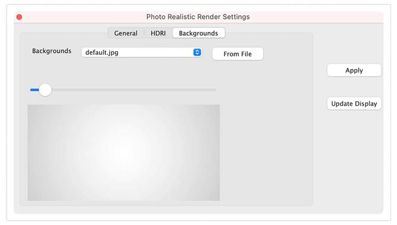
Backgrounds
The Backgrounds tab provides access to the following settings and parameters:
| Backgrounds | Drop drown containing example background images |
| From File | Select a background from file system |
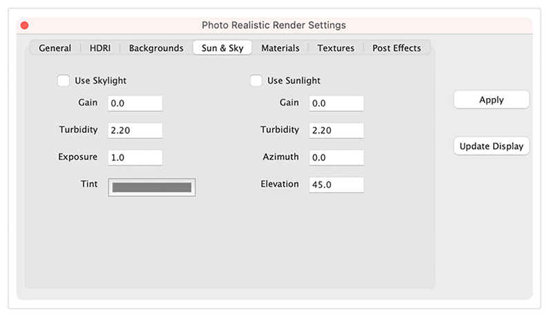
Sun & Sky
The Sun & Sky tab provides access to the following settings and parameters:
Use Skylight - Enables SkyLight environment lighting
Skylight Gain - Increase or decrease overall brightness
Skylight Turbidity- Increase or decrease atmosphere turbulence
Skylight Exposure- Increase or decrease overall intensity
Skylight Tint- Controls the color of the light
Use Sunlight- Enables Sunlight environment lighting
Sunlight Gain- Increase or decrease overall brightness
Sunlight Turbidity- Increase or decrease atmosphere turbulence
Sunlight Exposure- Increase or decrease overall intensity
Sunlight Tint- Controls the color of the light
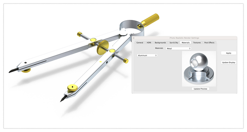
Materials
The Materials tab provides access to the following material settings and parameters:
Materials- List of material shader types
Each material can have a set of unique parameters. For example, glossy has:
Diffuse- Base color of object
Specular- Highlight color when light is perpendicular to surface normal
Roughness- How smooth or rough the material surface
Transparency- Material value for transparency or opacity
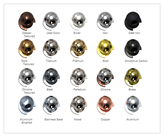
Materials: Metal Library
The Materials Metal shader provides access to a collection of preset metals that include silver, gold, chrome, copper, steel, nickel, and brass as examples.
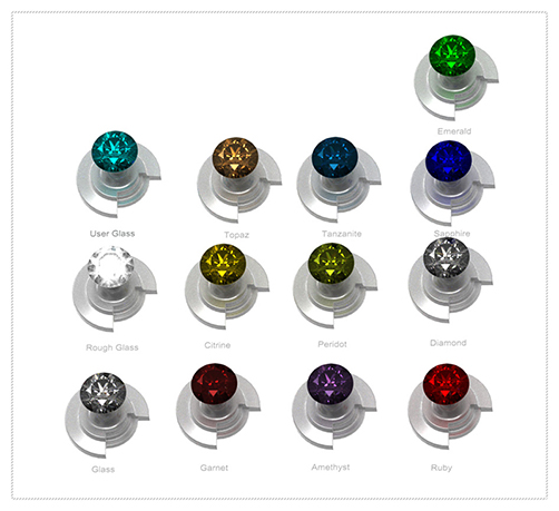
Materials: Glass Library
The Materials Glass shader provides access to a collection of preset glass and gemstones that include diamond, ruby, clear glass, and emerald.
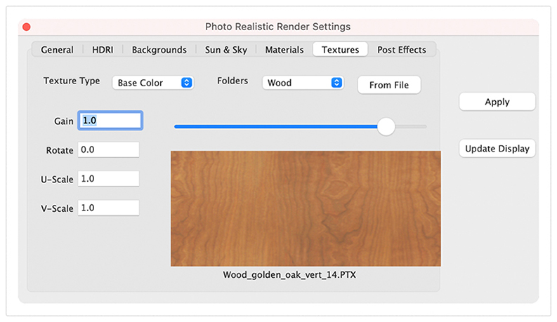
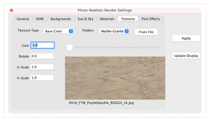
Textures
The Textures Tab provides access to a collection of preset textures that can be added to the material shader type on an object. Texture settings and parameters include:
Texture Type - List of existing textures
Folders - Textures organized by categories
From File - Select a texture from your file system
Gain - Increase or decrease the brightness of the texture
U-Scale - Scale the texture coordinates along u axis
V-Scale - Scale the texture coordinates along v axis
Post Effects
A post processor is a tool that allows you to apply various image-based effects to a rendered image after it has been completed. These effects can include things like tone mapping, denoising, color aberration, vignette, and gamma correction. Post processors can be very useful for improving the final appearance of a rendered image and can help to add a more polished and professional look to your work.
Post processors are accessed under the Post Effects tab in the render settings dialog box. The Post Effects tab is only available in SharkCAD, SharkCAD Pro, ViaCAD Pro, and TurboCAD Mac Pro.
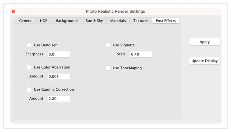
Denoiser
The denoiser used to reduce noise in images. The denoiser used is the Intel Open Image Denoiser (OIDN) which is based on a machine learning algorithm that has been trained on a large dataset of noisy and denoised images. This allows the denoiser to learn the patterns of noise present in different types of images, and to remove the noise while preserving the underlying detail and structure of the image.
To use OIDN, select the Post Effects tab and enable the “Use Denoiser” check box. The denoiser has one setting called Sharpness. By default, the Sharpness value for denoiser is set to zero which is “full” filtering. The value of 1 represents little to no denoising.
Note: The denoiser only works in CPU and will add a slight pause to each sample rendered.
Gamma Correction
Gamma Correction is a method used to adjust the brightness and contrast of an image by applying a nonlinear transformation to the pixel values. This transformation is typically used to correct for the nonlinear behavior of some displays, which can cause the displayed image to appear too dark or too bright.
Gamma correction is applied in the post-processing stage of the rendering process accessed by enabling the “Gamma Correction” check box. The “Amount” value specifies the exponent used in the nonlinear transformation, with a value of 2.2 being commonly used for sRGB displays.
By adjusting the "Gamma" value, you can adjust the overall brightness and contrast of the rendered image, as well as correct for any color shifts that may occur due to the nonlinear behavior of the display.
Tone Mapping
Tone mapping is the process of converting the high dynamic range (HDR) pixel values of a rendered image into low dynamic range (LDR) pixel values that can be displayed on a standard monitor. This is necessary because the dynamic range of an image, which is the range of luminance values from the darkest to the lightest parts of the image, is often much larger than the range of values that can be displayed on a standard monitor.
By adjusting the tone mapping parameters, you can control the overall appearance of the rendered image and make it more visually appealing.
To perform tone mapping, select the Post Effects tab and pick the “Tone Mapper” check box.
Vignette
Vignette is a post-processing effect that darkens the edges of an image, creating a concentric gradient from the center of the image to the edges. Vignette is often used to draw the viewer's attention towards the center of the image and create a sense of depth and focus.
To enable vignette, you can select the "Vignette" setting in the "Post Effects" tab of the render settings. When the "Vignette" setting is enabled, you can adjust the "Scale" parameter to control the strength and size of the vignette effect. The "Scale" parameter controls the size of the area affected by the vignette effect.
Color Aberration
Color aberration is a post-processing effect that simulates the chromatic aberration that can occur in real-world lenses. Chromatic aberration is an optical phenomenon that occurs when the different wavelengths of light are not focused on the same plane, causing different colors to appear slightly offset from one another. This can cause the edges of objects in an image to appear distorted or fringed with color.
To enable color aberration, pick the Post Effects tab and select the "Color Aberration" check box. When the "Color Aberration" setting is enabled, you can adjust the “Scale" parameter to control the size of the area affected by the color aberration effect. The "Scale" parameter specifies the size of the color fringes, with higher values resulting in larger fringes.
Photo Render Library
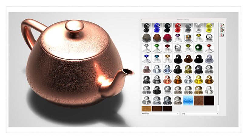
The Photo Render Library provides a collection of materials, HDRI, and backgrounds via a drag and drop user interface. To access the Library, select the Render Library from the Tools menu bar.
Materials/HDR/Backgrounds
The library category type provides access drag and drop materials, HDRI, backgrounds, and textures. Select a category such as materials to show various options for fabric, marble, glass, and metals. Position your cursor over the desired material and press and move to the object.
Laser Light
The laser light adds a direct light source that emits a focused beam of light. Laser Lights are defined by a start point, end point, radius, and gain. The start point defined the laser start while the end point defines the direction of the light. The radius value defines the cylinder region of light. The gain defines the strength of the light.

Paraboloid Primitive
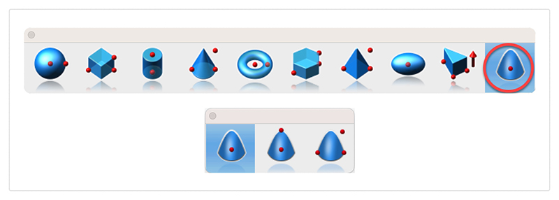
The paraboloid primitive provides a means to create a quadric surface from one-, two-, or three-point definitions. Use a paraboloid to create a reflectors/radars, automobile headlights, solar furnaces, antennas, and aerodynamic tips. The Paraboloid primitive is located in the solid primitives tool palette, last tool item. The one-point paraboloid has a base center, and three radius values. The two-point paraboloid has a base center, end. The three point has two points defining the base diagonal, and one point defining the height. Each method provides a data entry window interface to change the associated radius values.
Gripper Non-Uniform Scaling
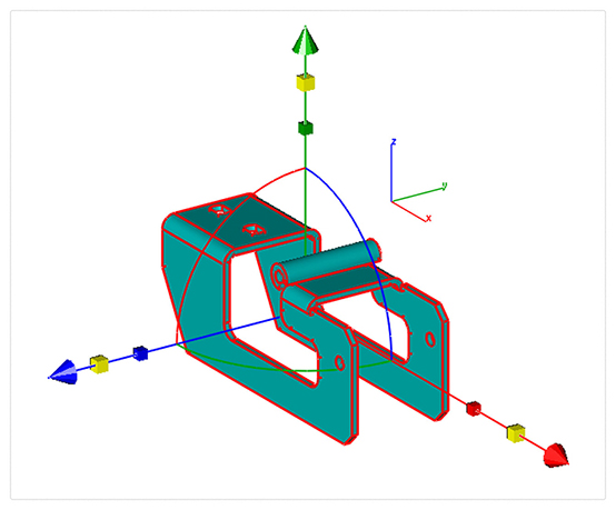
The Gripper has a new graphic widget to perform non uniform scaling via a handle. To use this feature, display the inspector and select the gripper properties tab. Then select “Enable Gripper”. The non-uniform scale graphic is the red, blue, or green box display along the associated axis. Select, hold and drag over the box to scale along that particular axis.
Red scales along x
Blue along y
And Green scales along z
You can scale curves, surfaces, or solids. Use the data entry window to scale a precise amount.
Area Dimension
A new dimension tool was introduced to support area-based measurements. To access the Area Dimension tool tear out the dimension tool palette and select the area dimension tool icon. The area dimension works with collections of closed curves or polygons. There are two options accessed through the data entry window.
1. Leader Line Dimension
2. Text at Centroid
Select Pick Leader Line Dimension. And now select the collection of curves or polygon. Then select the arrow location and text location. Now change the area method to text at centroid. And select the polygon. The area dimension is associative to the curves originally selected. Modifying a curve will update the area dimension. The Area dimension also work with a collection of curves used in a constrained system. In this case, updating any dimension value, will update the area dimension.

Spatial 2022 Update
Core technology components for the modeling and interoperability tools are provided by Dassault Systems Spatial Technology. V14 includes a major integration update for all products.
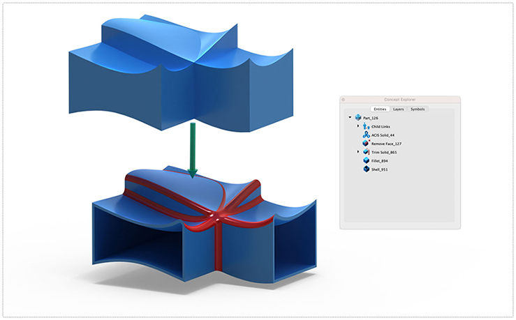
ACIS Modeling Kernel Update
The core modeling kernel was updated to support a newer version from Spatial. The new update provides greater increases in quality and robustness and improvements in modeling tasks such as booleans, blending, chamfering, sweeps, skinning, healing, and faceting functionality.
Interop Update
SAT & SAB UpdatesThe SAT and SAB data translators provide a neutral file format for precisely sharing curve, surface, and solid modeling data. Third party app supporting SAT/SAB file formats include AutoCAD, Inventor, Fusion 360, SolidWorks, and SolidEdge.
STEP & IGES UpdatesThe STEP and IGES translators for importing and exporting of precision curves, surfaces, and solids was updated via the Spatial Interop. STEP and IGES support sharing of precise NURB and analytic surfaces between applications.
SolidWorks, CATIA, PROE, NXNative format translators were updated to support newer versions from SolidWorks, SolidEdge, PRO E, CATIA, and NX.
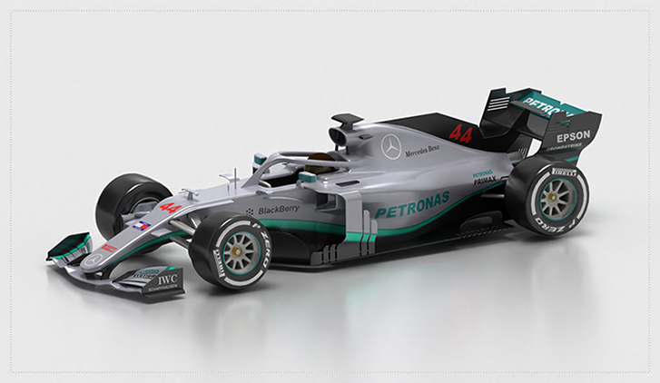
The 2D PDF export is a new method of sharing vector and font-based data with other applications. Vector data such as Lines, arc, circles, and splines are supported. Additionally, text and dimensions annotations are supported. Line styles and pen weights are also supported. Surfaces and Solids are exported as wireframes.
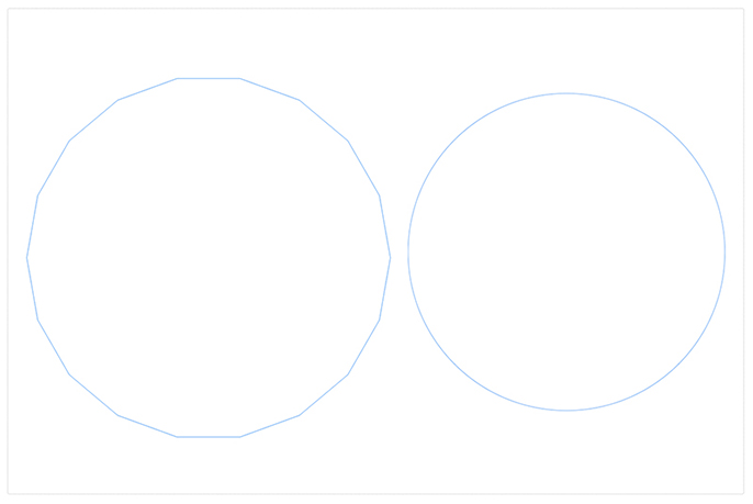
The DWG, DXF, PDF, and DAE translators provided through the Open Design Alliance (ODA) were updated to support the latest enhancements and performance boasts. Additionally, minor enhancements were made supporting sharing of text and dimension data.
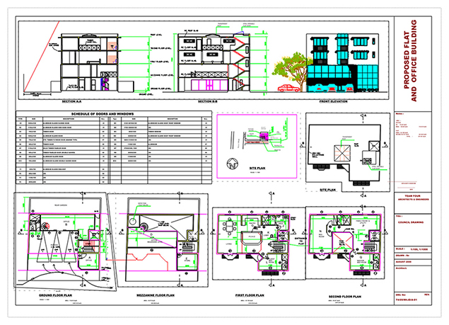
The SketchUp import/export technology was updated to support the lasted SDK. This includes support for newer versions as well as maintenance updates for sharing data between the applications.
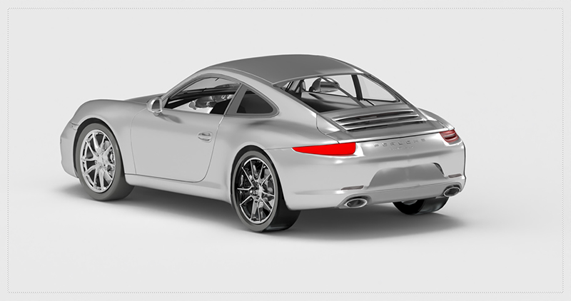
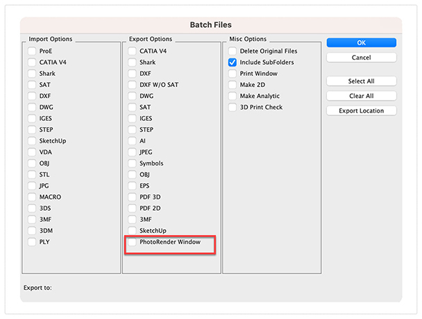
The Batch tool supports the option to render multiple images from a collection of files.
The tool will support rendering all cameras in visible layers of the files as well as use saved render settings. If no camera or saved render settings are present, it will use defaults at the time the batch tool was executed.
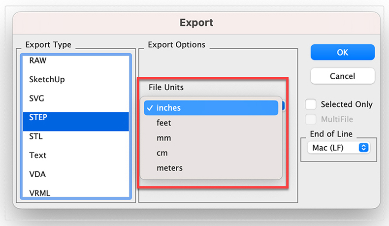
The STEP export file was updated to support specifying a unit setting upon export. Applications reading the STEP file must support reading the file unit setting.
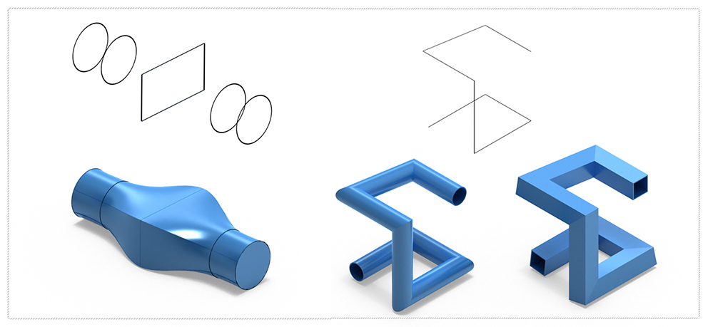
Ten new solid modeling tools were added into ViaCAD 2D3D and TurboCAD Mac Deluxe. These tools extend the already powerful solid modeling capability with the following tools:
- Two rail sweep
- Cutout Solid
- Protruded Solid
- Skin Solid
- Pipe
- Hole
- Boss
- Trim
- Push/Pull
 |
 |
 |
 |
 |
 |
Windows Recommended Requirements:
Microsoft® Windows® 64-Bit versions of Windows® 7, 8,10 , or 11 Intel® Pentium® IV or AMD® Athlon64™ class 64-bit processor 3 GB of hard disk space 8 GB of RAM Mouse Pointing Device (wheel button recommended) OpenGL/DirectX9 Compliant video card with 256MB of dedicated RAM
Macintosh Recommended Requirements:
Macintosh® OS 10.11 through 11.01 or higher¹ x64 Intel® Mac® 3 GB of hard disk space 8 GB RAM or greater Mouse Pointing Device (wheel button recommended) OpenGL Compliant video card with 256 MB VRAM ¹ Program compatibility is not guaranteed for later operating systems ²User is responsible for all Internet access fees and phone charges. PC & Mac require a machine with an operating system using x64 (64-Bit) architecture.

