Punch! ViaCAD v14 2D3D & Training Guide Bundle
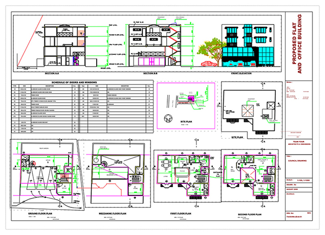
With ViaCAD® 2D/3D, the power of 3D design has never been easier. Our CAD software will allow you to design anything you can dream up, including architectural plans, mechanical plans, electrical schematics, furniture designs, and more. All you need is an idea and ViaCAD.
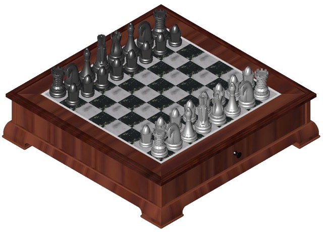
Our surprisingly affordable 2D and 3D design tool really packs a Punch! You can draft 2D projects such as floor plans and diagrams, but also create spectacular 3D designs for building construction, home renovation, inventions, musical instruments, furniture, and really fun DIY projects using a 3D printer at home or in the classroom. Suitable for beginners and intermediate users.

As low as
$249.99
Availability:
In stock
SKU
4605
Affordable 2D/3D CAD software that is extremely powerful and easy to use
ViaCAD 2D/3D offers precision design tools for beginning to intermediate CAD software users. It allows you to create in 2D or 3D and quickly toggle between views. Our price to performance ratio blows the competition away. Amateur users will be thrilled by professional-looking results, while professionals will love how budget-friendly this version of ViaCAD is. You may also want to check out ViaCAD Pro here.
ViaCAD 2D/3D can help you design projects such as:
|
 |
Compatibility and file sharing
ViaCAD software plays nice with others. ViaCAD is compatible with AutoCAD® with up-to-date DWG import and export capabilities. So your team will be able to work together without forcing everyone to be on the same brand of CAD software.
ViaCAD is also compatible with over a dozen popular CAD and Graphics formats, so you’ll be able to deliver files that can be opened and edited by users of other popular design software.
|
 |
We will help you learn
While ViaCAD is feature rich, we work hard at making it easy by including intuitive tools like our LogiCursor™ that makes CAD a snap by suggesting your next move as you draw.
Your purchase includes access to our training tutorials, so you will not have to learn through trial and error. We are experts at creating CAD software and our tutorials will help you to become an expert user quickly.
Write Your Own Review
ViaCAD 2D/3D is packed with 3D modeling and 2D drafting tools
Make your designs come to life with our powerful 3D CAD software. Begin exploring the powerful world of 3D mesh modeling! ViaCAD provides solid modeling technology found in many higher-end products. There is behind-the-scenes programming that connects 2D and 3D, so that you can edit 2D profiles used to create 3D objects and the 3D shape will automatically update.
- Powerful 3D design tools including mesh, surface, and solid modeling
- 3D editing tools such as blending, chamfering, and shelling
- Complete design tool with extrusions, Booleans, and surface modeling.
- Precise geometry suitable for ‘concept to manufacturing’
- Automatically generate 2D drawings from 3D models
- Tools to create 3D from 2D shapes
- Over 275 tools for 2D drafting (text, dimensions, points, lines, arcs, etc.)
- 3D printing verification tools
- And much more!
Intuitive Design and Editing Utilities
Drawing precisely is easy with ViaCAD! We have designed it to be user friendly and intuitive to work with.
The LogiCursor™ anticipates your next action and guides your cursor to potential point selections in the drawing.
The Gripper adds drag and drop capabilities to make editing designs easy breezy.
Customizable Grids add another level of ease by providing precision drag and drop in rectangular, polar (circular), and isometric layouts.
3D Printing Tools
ViaCAD 2D/3D includes 3D printing tools to prepare and validate your designs to make them 3D printer ready.
3D Print Check
Checks for print viability, displaying warnings or errors to the user.
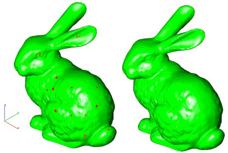
Surface Normals Check
Facet normals define the inside and outside areas of a part. If facet normals are pointing the wrong way, the 3D printer may have problems creating the part. This will check for problems and we have several commands that can help you fix it.
Overhang Analysis
This will help you visually inspect modeling areas that may require structural support for 3D printing. Meshes, surfaces, and solids facets normals are compared to the work plane direction. Angles that are less or equal to 45 degrees are highlighted as red.
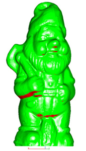
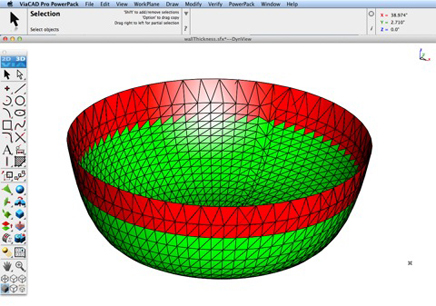
Wall Thickness Analysis
This tool provides a means to visually inspect modeling areas that may be too thin for 3D printing. Meshes, surfaces, and solids facets are examined using ray intersections.
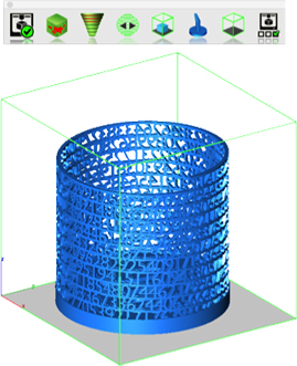
Preview Slices
This interface will help you to slice models given a direction and thickness. The dialog box allows for animation through the slices and single-stepping. Use to verify that a part has closed, non-overlapping sections, a requirement for 3D printing.
Auto Position
The Auto Position tool translates the model to the positive x, y coordinate system at z=0.
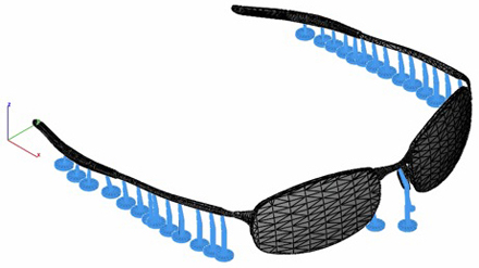
Support Structure
Manually adds geometry to support material as it is created by the 3D printer. Support structures controls, include Attach Radius, Midpoint Radius, Base Radius, Base Thickness, and Drag base and midpoints to modify structure location.
Show Printer Volume
Toggles the boundary of the default 3D Printer. The volume is defined within the Printer Definitions dialog box.
Printer Definitions
Sets key parameters of the 3D printer, including length, width, and height of the volume accessible by the printer. The parameters in the Printer Definitions dialog box are used for commands such as 3D Print Check and Auto Position.
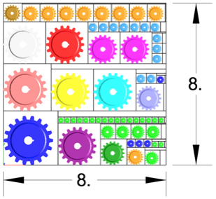
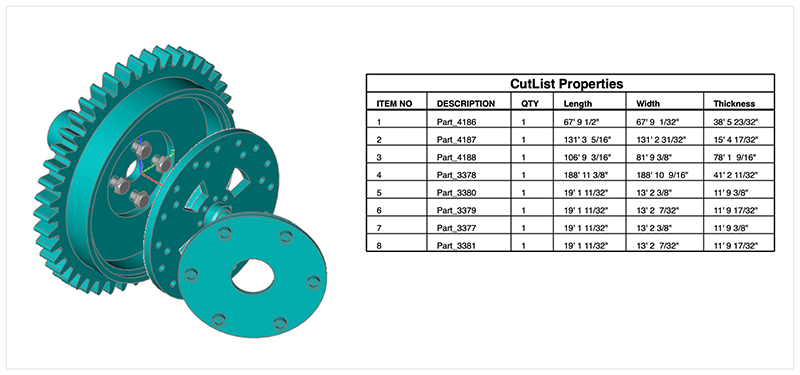
BOM Fraction Measurements
The Bill of Material Create BOM feature has a new option to support fraction measurements. To use this feature, select the Attributes and BOM dialog box from the Tools menu. Select your objects and associated a data set such as CutList properties. Apply to selected. Now select the Create BOM option to create a table. In the BOM Settings dialog box, select the Decimals pull down option. And then Select Fractions to display measurements as factions of feet and inches.
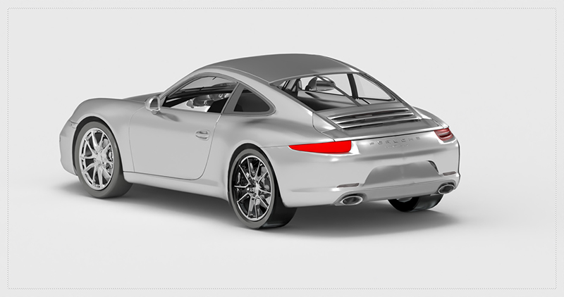
PBR Photo Rendering
PBR, or physically based rendering, is a method of rendering computer graphics that aims to accurately represent the way that light interacts with different materials in the real world. In PBR rendering, the appearance of a material is defined by a set of parameters that describe its physical properties, such as its roughness, reflectivity, and transparency. These parameters are used to calculate the way that light reflects off the surface of the material, taking into account the angle of the light source and the surface normal, as well as the surface's roughness and other properties.
One of the key benefits of PBR rendering is that it allows for more realistic and consistent results, as it is based on the physical properties of real-world materials rather than arbitrary artistic choices. This makes it particularly well-suited for applications where photorealism is important, such as architectural visualization, product design, and film and game development.
Key user interface components to PBR rendering include:
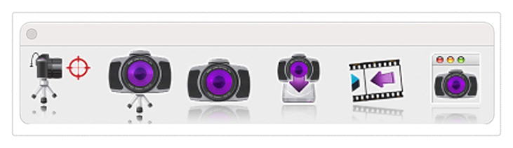
• Photo Render Tool Palette
• Rendering Cameras
• Render To File
• Render Window
• Render Settings
For a quick introduction to Photo Rendering with V14 see the video below:
Photo Render Tool Palette
The Photo Render tool palette provides access to many of the tools used to create photo rendered images. The tool palette is access from the Tools menu bar “Photo Render” option.
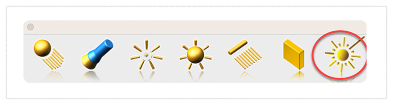
Laser Light
The laser light adds a direct light source that emits a focused beam of light. Laser Lights are defined by a start point, end point, radius, and gain. The start point defined the laser start while the end point defines the direction of the light. The radius value defines the cylinder region of light. The gain defines the strength of the light.
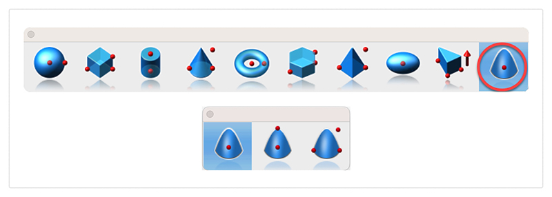
Paraboloid Primitive
The paraboloid primitive provides a means to create a quadric surface from one-, two-, or three-point definitions. Use a paraboloid to create a reflectors/radars, automobile headlights, solar furnaces, antennas, and aerodynamic tips. The Paraboloid primitive is located in the solid primitives tool palette, last tool item. The one-point paraboloid has a base center, and three radius values. The two-point paraboloid has a base center, end. The three point has two points defining the base diagonal, and one point defining the height. Each method provides a data entry window interface to change the associated radius values.
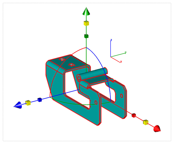
Gripper Non-Uniform Scaling
The Gripper has a new graphic widget to perform non uniform scaling via a handle. To use this feature, display the inspector and select the gripper properties tab. Then select “Enable Gripper”. The non-uniform scale graphic is the red, blue, or green box display along the associated axis. Select, hold and drag over the box to scale along that particular axis.
Red scales along x
Blue along y
And Green scales along z
You can scale curves, surfaces, or solids. Use the data entry window to scale a precise amount.
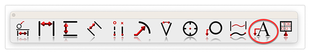
Area Dimension
A new dimension tool was introduced to support area-based measurements. To access the Area Dimension tool tear out the dimension tool palette and select the area dimension tool icon. The area dimension works with collections of closed curves or polygons. There are two options accessed through the data entry window.
1. Leader Line Dimension
2. Text at Centroid
Select Pick Leader Line Dimension. And now select the collection of curves or polygon. Then select the arrow location and text location. Now change the area method to text at centroid. And select the polygon. The area dimension is associative to the curves originally selected. Modifying a curve will update the area dimension. The Area dimension also work with a collection of curves used in a constrained system. In this case, updating any dimension value, will update the area dimension.
ACIS Modeling Kernel Update
The core modeling kernel was updated to support a newer version from Spatial. The new update provides greater increases in quality and robustness and improvements in modeling tasks such as booleans, blending, chamfering, sweeps, skinning, healing, and faceting functionality.
Interop Update
SAT & SAB UpdatesThe SAT and SAB data translators provide a neutral file format for precisely sharing curve, surface, and solid modeling data. Third party app supporting SAT/SAB file formats include AutoCAD, Inventor, Fusion 360, SolidWorks, and SolidEdge.
2D PDF ExportThe 2D PDF export is a new method of sharing vector and font-based data with other applications. Vector data such as Lines, arc, circles, and splines are supported. Additionally, text and dimensions annotations are supported. Line styles and pen weights are also supported. Surfaces and Solids are exported as wireframes.
The DWG, DXF, PDF, and DAE translators provided through the Open Design Alliance (ODA) were updated to support the latest enhancements and performance boasts. Additionally, minor enhancements were made supporting sharing of text and dimension data.
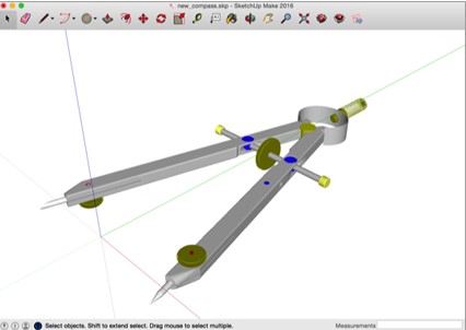
The SketchUp import/export technology was updated to support the lasted SDK. This includes support for newer versions as well as maintenance updates for sharing data between the applications.
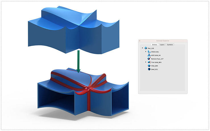
Ten new solid modeling tools were added into ViaCAD 2D3D. These tools extend the already powerful solid modeling capability with the following tools:
- Two rail sweep
- Cutout Solid
- Protruded Solid
- Skin Solid
- Pipe
- Hole
- Boss
- Trim
- Push/Pull
10 fully detailed sections on all the tools most frequently used in any 2D or 3D Design. Some of these include :
- The Graphical User Interface
- Sketch Creation Tools
- Selection & Manipulation Tools
- Modification & Information
- Annotation tools
- Creating Drawing Layouts
- 3D Modeling Tools
- Woodworking Tools
- Function & Operational Tools such as creating customizable Context Menus & Shortcuts and adjusting the Griper Properties.
2D & 3D Self-Paced Tutorials
Also includes 16 self-paced Work sessions containing the 2D Sketch and 3D Model of the same design. Each Worksheet contains detailed, colorful instructions on how to complete each task, including full animations per task. Each task contains full instructions in an animated, video format. Pause, rewind, or fast-forward your videos while you draw. Drag the movie to another screen and use the instructions on your laptop to produce the designs and the movie on the second screen to check your progress.
Progress through each session at your own pace, repeating any task as many times as necessary until you are ready to move to the next design. Tutorials 4 to 8 contain a full 5-part component to assembly design, progressively building the design with each tutorial. Access the PunchCAD Forum and Online User Guides for additional information from within your Training Guide. Get expert support from our Team from within your Training Guide.
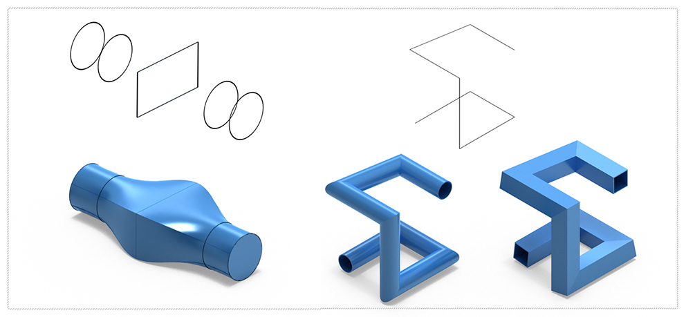
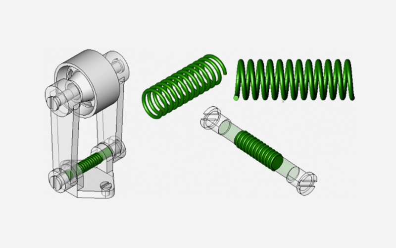
Sample 1 | Helix and Pipe:
Sweeping a circle along a path to create the helix. Creating a Pipe from a single line to form an axis.
Sample 2 | Creating a Slotted Wheel:
Using the Lathe tool to create a solid.
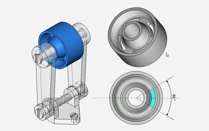
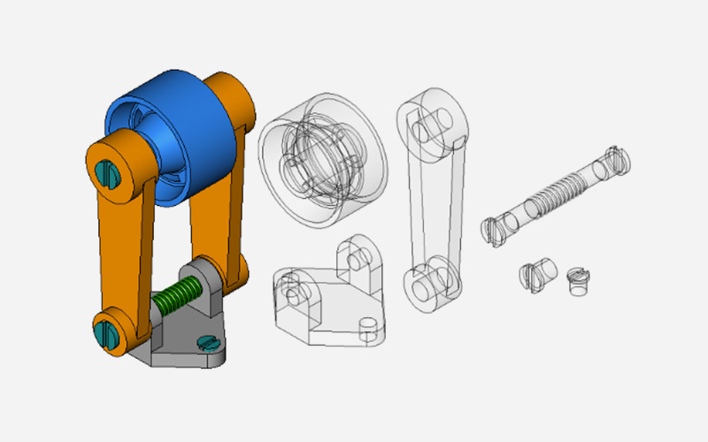
Sample 3 | Assembling a Part:
Learn how to design using the component-assembly method commonly used in the industry. Assemble multiple parts in the same design and to create a highly organized drawing with Layers and Sub-Layers allowing complete control over each component.
Windows Recommended Requirements:
Microsoft® Windows® 64-Bit versions of Windows® 7, 8,10 , or 11 Intel® Pentium® IV or AMD® Athlon64™ class 64-bit processor 3 GB of hard disk space 8 GB of RAM Mouse Pointing Device (wheel button recommended) OpenGL/DirectX9 Compliant video card with 256MB of dedicated RAM
Macintosh Recommended Requirements:
Macintosh® OS 10.11 through 11.01 or higher¹ x64 Intel® Mac® 3 GB of hard disk space 8 GB RAM or greater Mouse Pointing Device (wheel button recommended) OpenGL Compliant video card with 256 MB VRAM ¹ Program compatibility is not guaranteed for later operating systems ²User is responsible for all Internet access fees and phone charges. PC & Mac require a machine with an operating system using x64 (64-Bit) architecture.